- Your cart is empty
- Continue Shopping

Product
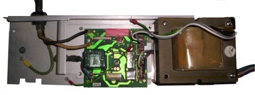
Remove/Replace Power Supply PCB. Hazardous voltages are present in the instrument when the power cord is connected. Avoid a potentially dangerous shock hazard by disconnecting the power cord before working on the instrument.
Set the main power line switch to the off position.
Disconnect the power cable from its receptacle.
Turn off all gas supplies.
Remove the four screws securing the rear cover to the instrument.
Slide the rear cover towards the rear of the instrument. This procedure requires precautions against ESD (Electro- Static Discharge). Use a grounded wrist strap (part no. 9300- 0969 – large, or 9300- 0970 – small) connected to a suitable ground. Failure to heed this caution may result in damage to the instrument.
Use a 7- mm nut driver to remove the screw
securing the upper portion of the dual duct assembly to the outer oven shell.
Use a Pozidriv screwdriver to loosen (but not remove, the screw securing the lower portion of the dual duct assembly to the outer oven shell.
Tilt the upper portion of the dual duct assembly out of the rear of the instrument while lifting it off of the loosened lower screw. When disconnecting a plug, pull on the plug not on its wires. Pulling on the wires may cause breakage.
Disconnect push- on type connectors J1, J2, J3, and J4 (from blade connectors P1, P2, P3, and P4, respectively) by grasping each one and pulling it straight off of its terminal.
Disconnect connectors J26, J27, and J28 from their respective receptacles. (Remove each one by squeezing its ribbed sides while simultaneously pulling it out of the receptacle.)
Use a 7mm nut driver to loosen, but not remove, the mounting nut corresponding to the mounting slot at the left edge of the AC power supply PCB mounting bracket, alongside the power transformer.
Use the nut driver to remove the two mounting nuts at the right edge of the AC power supply PCB mounting bracket.NOTE: The AC power supply PCB, and its associated mounting bracket, are removed and replaced as a unit.
Lift the PCB bracket at its right edge while sliding it to the right to remove it from the instrument.
Install the replacement AC power supply PCB in the reverse manner by sliding the mounting slot on the left side of the PCB mounting bracket under the loosened mounting screw adjacent to the transformer.
Install the two mounting nuts at the right edge of the AC power supply PCB mounting bracket.
Tighten the two mounting nuts and the mounting screw firmly.
Install connectors J26, J27, and J28 into their respective receptacles, pushing each straight down until fully bottomed.
Install push- on- type connectors for oven heater leads (J3 and J4). (Either lead may be connected to either terminal.)
Connect power cord lead push- on- type connectors J1 (WHITE lead) and J2 (BLACK lead).
Install the dual duct assembly on the installed mounting screw.
Install the upper mounting nut to secure the dual duct assembly to the outer oven shell.
Tighten the upper mounting nut using a 7- mm nut driver.
Tighten the lower mounting screw using a Pozidriv screwdriver.
Slide the rear cover on to the instrument.
Secure the rear cover to the instrument by installing and tightening four screws.
Restore all gas supplies.
Restore power to the instrument.
Observe the alphanumeric display, as the instrument performs an internal self- diagnostic integrity check. to ensure that the instrument shows the expected normal displays.


